SunSpec 4 Motor & Drive
Week 1
Task 1: Brushed DC Motor VS Brushless DC Motor(BLDC)
Differences on Brushed DC Motor & BLDC
Brushed DC Motor
The brushes inside the electric motor is used to transfer current to the motor windings through commutator contacts. Hence the windings is located at the rotor shown in Fig 1.
BLDC
The field inside a brushless motor is switched by an amplifier. Triggering by a commutating device eg, optical encoder. Hence the winding is located on the stator shown in Fig 2
Brushed Motor Advantages:
-
Brushed wire can be wired directly to DC power and control.
-
Low cost
Brushed Motor Disadvantages:
-
Low effieciency
-
Produce electrical noise as when the commutators switch constantly, it create and break inductive circuits.
-
Short lifespan as they are in perpetual physical contact with the shaft, brushes and commutators wear out
Brushless Motor Advantages:
-
High efficiency
-
Low maintenance and longer life span because it is brushless
Brushless Motor Disadvantages:
-
High initial cost as commutating device is needed such as encoder and a controller
Efficiency:
-
Brushless motors - around 85-90%
-
Brush motors - around 75-80%
Task 2: Popular motors used for Solar Car Race
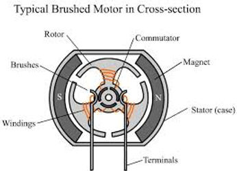

Fig 1
Fig 2
NuGen SCM150 (Wheel Mounted), With Controller
Introduction
SCM150 is an ultra-efficient Fig 3, 7.5 kW peak power motor especially designed for solar car applications where efficiency is key. An in-wheel motor having a variable gap mechanism that allows for the torque-speed characteristics to be changed on the fly. Used by more than 90% of solar car teams in the US.
Top finishers :
-
Sunrayce 99,
-
American Solar Race 2001,
-
American Solar Race 2003
-
American Solar Race 2005
Specification refer to Fig 4
Efficiency:
-
94%
Rated Power
-
7.5 kW
Max Speed
-
1300 RPM
Weight
-
20kg
Technology of motor:
-
High Power Rare Earth Permanent Magnets
-
Variable gap mechanism allows for torque constant to be changed on the fly.
Controller 96v Fig 5
EVC402-042/092 series controllers are 48/96 V controllers that are “plug & play” with SCM150 motors used in solar cars. They are ultra high efficiency sine wave controllers that provide regenerative braking. Capable of serial or discrete communication.
Cost
Single Motor$22,000 w/o controller
Conclusion
High efficency, high speed but high power consumption & very heavy.
Cost is also an issue.
Decision
Medium
CIRSO/ Marand, Wheel Motor, with and without rim, No Controller, Need third party
Introduction
The wheel has been designed for high strength and low weight, and eliminates the need for a drive train and the associated energy losses. Its low mass can be attributed to eliminating any material which is not absolutely required to maintain the performance of the motor.
CIRSO/Marand supplied with all components to be assembled onto the solar car including wiring harness for both power and controls, and three inductors usually necessary for connection between your chosen motor controller and the motor shown in
Fig 6.
Top finishers
-
Nuon University First in WSC 2013
Specification refer to Fig 7
Efficiency:
-
98.3%
Rated Power
-
1.8 kW
Nominal Speed
-
1060 RPM
Weight
-
15.40 kg
Technology
-
The stator windings have no iron core
-
Extensive weight reduction is carried out on the magnet backing plates in areas of low magnetic flux.
-
The Motor Frame has been CNC machined out of aerospace grade aluminium to be lightweight and maintain its strength under the high magnetic loads and driving forces.
-
The design keeps the entire mass of the wheel below 16kg
Cost
-
Single motor: AUD 26,000 w/o controller
-
Controller: WaveSculptor22 Motor Inverter AUD 6,000 Tritium
-
Total: AUD 64,000 for 2 pair
Conclusion
-
Very high efficency, medium light weight, low power consumption, speed is good but third party controller such as tritium is needed. Hence many balancing is needed and we need to calibrate the controller to achieve best performance
-
Due to time constraint, we go not have the time and skills to calibrate.
-
Cost is ok
Decision
Low
MITSUBA
4 models: M20100D-SP2013, M1096, M2096-ii & M2096-iii
Mitsuba M20100D-SP2013 (Wheel Mounted), Mitsuba controller included, Fig 8
Top finishers :
-
Tokai University
Efficiency:
-
98% with controller (M2096C)
Others specification not found.
Technology:
-
Brushless DC, Direct Drive,
-
Iron Based Amorphous Core
-
Use ceramic ball bearing to reduce fractional losses.Fig 9
Cost: Unknown
Information taken from: http://www.ei.u-tokai.ac.jp/kimura/kimura-lab/solarcar/2013wsci.html
Mitsuba M1096 (Wheel Mounted), Mitsuba controller M0896
SunSpec 3 use this model
Specification Fig 10.
Efficiency:
-
>94%
Rated Power
-
2.5kw depends on V & battery
Nominal Speed
-
675rpm
Weight
-
7.4kg
Technology:
-
Brushless DC, Direct Drive,
-
Iron Based Amorphous Core(TBC)
Cost: TBC
Mitsuba M1096-ii & M2096-iii (Wheel Mounted), with controller M2096c(Same as Tokai Uni)
Cross referencing with previous motor group. Firstly professional from Japan suggest SunSpec 4 to use a single unit of M2096 motor on one side of the wheels. This can help to reduce power consumption with only a single motor & controller. But feasibility studies proves that 2 unit of M2096 will be safer. Fig 11 shows the comparision of M1096 and M2096. The power table (Show some calculation from excel)
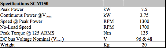
Fig 4

Fig 3

Fig 5
Week 2

Fig 7

Fig 6

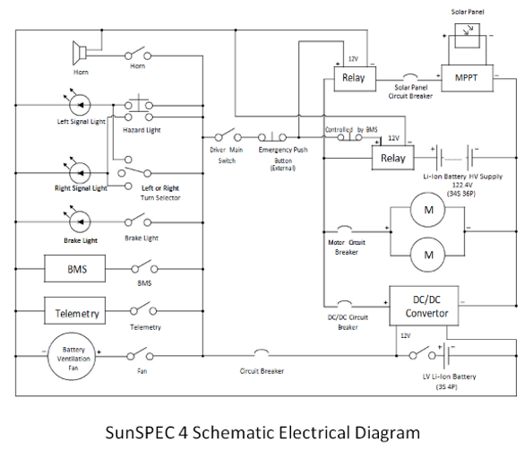
It is important for us to understand as we would be involving in the auxilary system. Also, we studied the other systems in our car to familiarize so that we would be ready for the race. Diagram found in figure 13.
There are total 4 parts of the solar panels namely A, B, C & D. D would be place inside the car for external charging. The solar panel that we're using is the Sunpower (~24%) Monocrystalline. The regulation state that we could have up to 6m2. We hope we could achieve about 1352.4w. Then it is connected to the MPPT"Drivetech" to achieve maximum possible power from the PV modules.
The battery we are suing is the Panasonic NCR 18650 Li-ion. We connect them in 34s 36p (1224pcs). Total power: 14.8kw.
The motor Mitsuba M2096-iii for the left and right will take electrical energy from the battery. DC/DC converter to step down to 12V to run auxilary devices eg, signal lights, horn etc
Rear or front wheel drive?
We research that there are more benefits of placing the motor at the rear than the front. The pros of placing the motor at the rear are the following:
Better weight distribution.
-
Exotic cars like Lamboghini place their engine at the back of their car. Hence due to its performance and weight distribution, their car runs on rear-wheel drive. Normal car like Toyota Estima. It is front wheel drive as the engine in place at the front.
-
SunSpec4 battery is place at the back of the car and passenger is more to the near centre. Hence weight distribution is an issue to be consider.
-
This can improve the handling, acceleration, braking, and thus safety of a car.
Better acceleration
-
Imagine youre sitting in a car at a stop. When the car accelerate, your body lean back and all weight will be disributed to the back. If the motor is place at the front wheel ,weight goes to the back, this will allow the front wheel to spin easier and the grip of the wheel to the road might reduce. This also affect the handling of the car.
-
Rear wheel drive with motor installed and the front tires are for steering of the car will be an ideal idea for good handling and acceleration.
No Torque Steer.
-
If the motor is place at the front. A problem known as Torque Steer.
-
This problem occur when the accleration of the motor effects the car steering. Rear car do not have this problem as it is not connected to the steering gear.
-
Hence callibration is not needed
-
Cheaper to maintain as it not connected to steering gear
After all consideration, SunSpec 4 will run on Real wheel drive. It benifit SunSpec 4 for its performace. Refer to figure 14.
Rear wheel drive of SunSpec 4
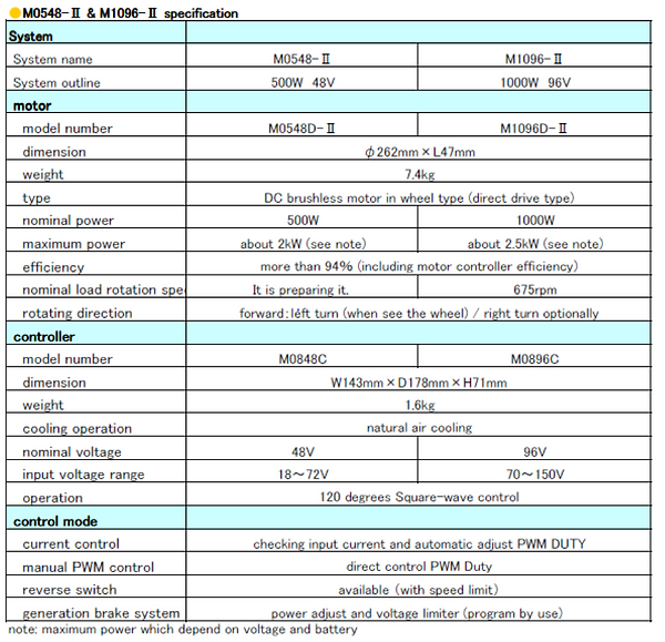

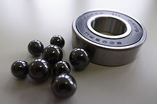
Fig 8
Fig 9
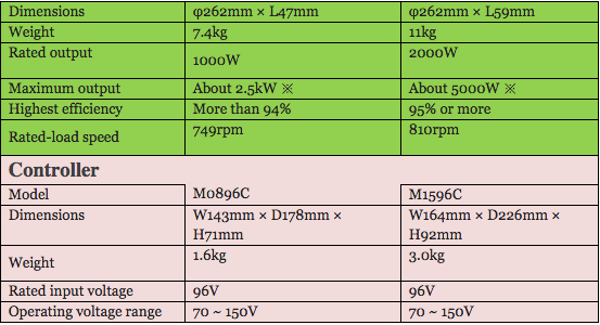
Fig 10
Fig 11 taken from previous group
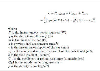
Fig 12 taken from previous group
Effects of low voltage on motors
In order to drive a fixed mechanical load connected to the shaft, a motor must draw a constant amount of power from the power line. The amount of power drawn from the motors is related to a formula of power equal to voltage times current. Therefore, the current will become higher when the voltage is too low in order to produce the same amount of power. Overload of current will build up the heat within the motor which will damage and shorten the motor life.
A reduction of voltage alwould reduce the starting torque, pull-up torque, and pull-out torque. Thus, we always have difficulty to start “hard-to-start” loads when the voltage is too low. Similarly the motor’s pull-out torque would be much lower than it would be under normal voltage conditions.
On lightly loaded motors with easy-to-start loads, reducing the voltage will not have any appreciable effect except that it might help reduce the light load losses and improve the efficiency under this condition.
Effects of high voltage on motor
High voltage on a motor tends to push the magnetic portion of the motor into saturation. This causes the motor to draw excessive current in an effort to magnetise the iron beyond the point where it can easily be magnetised. Heat begins to build up in the motors and damage it. Motors will tolerate a certain change in voltage above the design voltage. However, too high of voltage will cause the current to increase which corresponding to build up heat in motors. Normally, motors have a tolerance band of plus/minus 10% of rated voltage. This mean motors rated at 220/440 can tolerate on high voltage connections of 396 to 484. However, motors have the best performance at the rated voltage. Either ttoo high or low of voltage will decrease the motor efficiency.
Week 3 & 4
Task 1: Understanding the circuit diagram of SunSpec 4.
Task 2: Positioning of motor
Task 3: Understand HV & LV
Task 1: Average power from Sunpower Solar panel and NCR 18650 B 34S36P batterries
Firstly, our targeted average speed would be 70km/hr and our power consumption of the motor is about 1400W.
Our batteries will be fully charged from Day 1 to Day 3 and the charging station would be at Alice Spring on Day 3. After that, Day 4 to Day 6 with fully charged batteries.
Batteries in 34S36P : 15KW
Solar panel will be splited into 4 parts namely A,B,C and D. A,B and C will be on the top of the car and D will be kept inside the car for morning and evening charging. 6m2 approx will provide total of 19.5kw in 3 days.
Solar + Batteries=34.5kw in 3days
From our desire average speed 70km/h, total power will be approx 31.5kw. Therefore, our solar car is expected to reach Alice spring with some energy left on batteries before charging. Diagram can be seen at Fig 15.

Conclusion:
Mitsuba has a passion on Solar Car Race. They have a project that is going on and hoping every solar car is top notch. Hence, they also did various motors for electric vehicle. So far Mitsuba invent high efficiency electric motor and also controllers.
Mitsuba produce low power consumption yet good efficiency, torque and light weight. It comes with its very own controller for its motor. This help in balancing the speed of the motor at either side. It consumes minimal power. They use Iron Based Amorphous Core. This helps to improve energy efficient and lighted weight.
Why we choose Mitsuba 1096D-lll & Mitsuba 2096D-ll?
The motor that we used for Sunspec 3 which is the Mitsuba M1096D has a power rating of 1 KW. For Sunspec 4, the motor we will use is Mitsuba M2096D-III which has a power rating of 2 KW. The main reason why we use M2096D-III motor is because the power required to move SunSpec4 is greater compared to SunSpec3 because we are entering the cruiser class race which requires a passenger.
Both M1096D-II and M2096D-III have the same power output. However, the reason we choose M2096D-III over M1096D-II to install on our solar car is because M2096D-III use Iron Based Amorphous Core which improve energy efficient and lighted weight. We had ordered each pair of M1096D-II and M2096D-III. However, we will be using two units of M2096D-III on Sunspec 4 as we have done many calculations to prove that it is more feasible. M1096D-II motors are the spare in case the M2096D-III fails to reach its performance.
Task 2: Analyzing 0KM-496KM power Darwin-Larrimah
First 113km summary, Darwin to Adelaide River
0-30km :Flagging of from Hidden Valley, car convoy and traffic lights. City area might have schools. Hence starting accelration might be needed if stop. Some high power occur might due to this problems
Noted: Slopes spotted at :
3km-6km in figure 19 (250m of Up & Down Slope)
9.5km-10km in figure 20 (450m of Up & Down Slope)
23km-23.8km in figure 21 (800m Gentle up slope)
25km-27km in figure 22(Down slope)
27.2km-27.89km in figure 23(400m of Up slope)
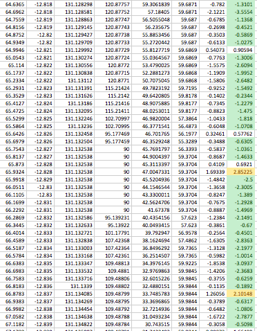
From the excel sheet for the first 500km, we break down to per km to find out the power used for each km.
Legend: Green <0w
Yellow >20w
Red>35w
Avg power: 21w per box

Fig 13 Circuit Diagram of SunSpec 4
Fig 14
Fig 15
Fig 17, Darwin to Humpty Doo approx 30km
Fig 16 1km to 113km
Fig 19

Fig 20

Fig 24 0-113km: Hidden Valley to Adl River.
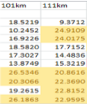


Fig 18, power consumed per km


Fig 21
Fig 22
Fig 23

End of 0km-30km summary

>30km to to Adelaide River
30km-113km : More away from the busy city. Smoother ride as power is gradual. Some power in red might occur due to overtaking of other teams or unstable acceleration.
41km-60km : We retify there are no high gradient.
60km-80km: Very light up gradient, down slope is found also in figure 25
80km-113km: Up & Down slope which balance the power in figure 26

Fig 25


Fig 26

End of 0km-113km summary
Adelaide River to Pine Creek 113km-227km


Fig 26 113km-227km Adelaide River to Pine Creek
Fig 27 113km-227km
From 113km-227km, many red spot are spotted and less regenerative braking occur during this strech.
113km-140km:
126km has a red spot but there is down slope(800m), hence it might due to improper acceleration. Refer to figure 28
141km-160km:
148km has a gradient (800m). Refer to figure 29
161km-190km:
163km-164km have Up & Down slope hence, constant acceleration needed (600m) Refer to figure 30
171km-174km:
At 171km stretch, (420m) of up slope and its consume quite a lot of power. Refer to figure 31
At 174km,(420m) consume lots of power due to heavy slopes.Refer to figure 32
181km-227km:
No high gradient spotted but red spot might be due to over-taking or improper acceleration.
Our group plan to toll from 160km to 190km as it is consuming lots of power.


Fig 28


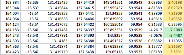
Fig 32
Fig 31
Fig 30
Fig 29

End of 113km-227km summary
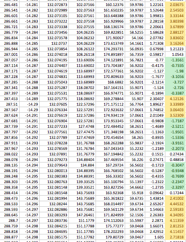
Pine Creek-Katherine 227km-317km
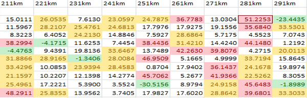
Fig 33 Pine Creek-Katherine 227km-317km
Fig 34

From 227km-314km, there are some red spot and power used here is quite high in average. Fig 34
From 221km-250km:
Smooth ride
254km-260km:
Up slope found inbetween this stretch. Regenerative braking is also found at this stretch. Refer to fig 35
261km-281km:
Gradient is very constant and light. Many small down slope along this stretch. At 281km(400m) of slope is found. Refer to fig_
282km-290km:
Many red spot spotted in this stretch. But the gradient are shallow. From 286km to 290km, Up slopes found but 2 slopes are found to be 420m each. 3 Gentle down slope runs about 420m each which doesnt require much power in fig 36
291km-314km:
Smooth rides but power is quite high might be due to improper acceleration or overtaking. No heavy gradient spotted.
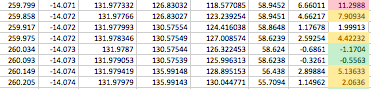

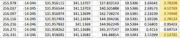

Fig 35
Fig 36

End of 227km-317km summary
Katherine to Mataranka 317km-421km

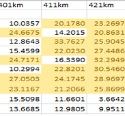


Fig 37
Fig 38
From 317km-421km, power consumption is stable, looking at the terrain excel sheet, road is almost flat but with about 60m of slope that makes the red spot. Refer to fig 38

End of 317km-421km summary
Mataranka to Larrimah 421km-496km
Fig 39 Mataranka to Larrimah 421km-496km
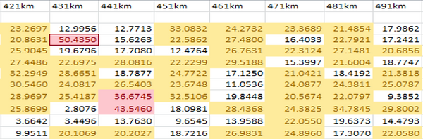
Fig 40, power consume per km

From 421km-496km, we can see the power consume is stable but for a few part of red spot, we cross check with the excel sheet on terrain that only about 240m slope at 432km. The other 2 spot might be due to improper acceleration or overtaking.
End of 421km-496km summary
Task 3: Analyzing 496KM-985KM power
Larrimah-Tennant Creek

Larrimah-Daly Waters 496km-583km


Fig 41, Larrimah-Daly Waters
Fig 42 Power consumption from 496km to 583km
From 496km-583km, throught this 87km route shows a constant power. As we cross reference to the terrain from the excel file, no heavy gradient but the average of this stretch is almost flat but there are still a bit of 60m hills. At 498km, it spike up to nearly 30w but no graident found at the excel file.

Daly Waters-Dunmarra 583km-633km
Fig 42, Daly Waters- Dunmarra 583km-633km


Fig 43, Daly Waters-Dunmarra 583km-633km
From 583km-633km, power is constant throughout this stretch as it falls between the average power of 21w. As shown in figure 44, this road is about 2km long and is almost flat and maybe can consider constant and light acceleration to save energy.
But when we zoom into 605km(red spot) in figure 45 , we didn't spot any heavy gradient.
627km-630km:
Power consume is low due to down slope gradient. Refer to fig 47.


Fig 45
Fig 47
Fig 44

Fig 46
End of 583km-633km summary
End of 496km to 583km summary

Dunmarra- Newcastle Waters 633km-710km
Fig 48, Dunmarra- Newcastle Waters 633km-710km


Fig 49, Power consumed from 633km-710km

From 633km-69okm, the power consume falls between the average power. The road is almost flat when cross reference to the road terrain on the excel sheet.
698km-700km:
But we zoom into the excel sheet in figure 50. We didn't observe any heavy gradient. It might be due to overtaking or improper acceleration.
709km-710km:
But we zoom into the excel sheet in figure 51. We didn't observe any heavy gradient. It might be due to overtaking or improper acceleration.

Fig 51
Fig 50


Newcastle Waters - Tennant Creek 710km-985km

End of 633km-710km summary
Fig 52, Newcastle Waters- Tennant Creek 710km-985km
Fig 53, 711km-800km
Fig 56, 801km- 900km
Fig 58, 901km-981km

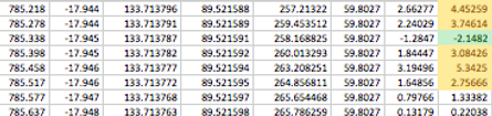

Fig 54
Fig 56
Fig 55
From 711km-791km, we can conclude its a smooth ride across this route.
738km-740km:
The power consume at 739km for 60m has a high gradient but if we could control properly, no tow is needed shown in fig 54.
764-765km:
120m slopes spotted, hence proper acceleration must be implemented.Figure 55
784km-786km:
Slope spotted but power consume is good. Driver can drive very well. Figure 56
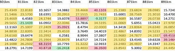
801KM-900KM
From 801km-900km, there are a few small slopes about 120m maximum across this route.
But for 897km-900km:
No slopes found but maybe over taking or improper might cause this spike.Figure 57.

Fig 57
901KM-981KM
From 901km-981km, no heavy slopes spotted.
924km-925,5km:
But here, we found a small stretch of road about 1km with uneven terrain but not much energy consuming. Figure 59
978km-979km:
Quite a lot of power used in this stretch. But the gradient is negative and its assume to be picking up speed. Seen in figure 60.


Fig 59
Fig 60
About 1km out of Tennant Creek, there is a small hill that requires a little more energy to go over however the energy regained by regenerative braking will balance out the power used.
The Solar Car is going at constant speed with a stable gradient thus there are only slight changes with the energy consumption.
More energy are taken from 1085km is probably due to acceleration of the car because there are minimum changes to the gradient during that 1km. Refer to figure 61.
Tennant Creek – Wauchope (985km to 1101km)

Wauchope – Barrow Creek (1101km to 1210km)

The journey from Wauchope to Barrow Creek does not have any major gradient changes. The increase in energy consumption is probably due to acceleration of the car. There is an increase in gradient between 1200km to 1201km but the energy consumption is not very high because of the regenerative braking. Refer to figure 63


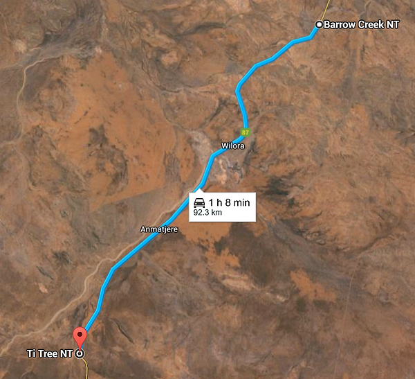
Barrow Creek - Ti Tree (1210km to 1299km)

The first few km between Barrow Creek to Ti Tree has a slight increase in gradient. Furthermore, there is a major increase in gradient around 1234km to 1236km. The gradient remain mostly stable for the rest of the journey between Barrow Creek to Ti Tree. Refer to figure 65.
Ti Tree - Aileron (1299km to 1385km)
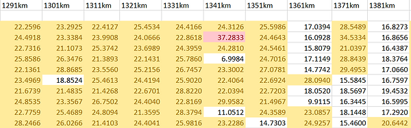
The Journey between Ti Tree to Aileron seem to have only slight changes in the gradient. However, at 1353km the is a increase in gradient. The increase in power consumption at 1342km is probably due to acceleration on the car as there are no obvious change in gradient. Refer to figure 67.

Aileron - Alice Spring (1385km-1494km)

The journey from Aileron to Alice Spring also have very slight changes in gradient, only a slope around 1481km. Refer to figure 68.

Week 5
DC-DC converters for auxilary devices.


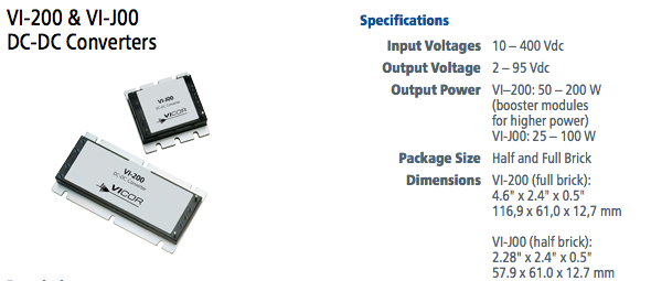
According to the specification,
Input Voltages: 120v-150v
Output Voltage: 12v
Output Power: 100w
So we search online and we found a leading brand VICOR that meets our requirements.
VICOR has 2 models,
VI-200 (Full Brick)
VI-J00 (Half Brick)
The different between half and full is the range of the output power. Refer to figure 70
Fig 61
Fig 62
Fig 63
Fig 64
Fig 65
Fig 66
Fig 67
Fig 67
Fig 68
Fig 69
Fig 70
We did a purchase by our specification with VICOR.
We bought 2 pcs and the part number could been seen at figure 71.
Fig 70
Week 5
Task 1: Learning how to change tire for SunSpec 4
We seek the MAE team for sometime to teach us how to change the tire for our solar car. This can help us to be prepare for the race.

Step 1: Remove the tire from the car.

Figure 72 shows Carbon fibre rims
16 Inches
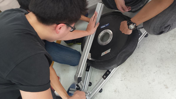
Step 2: Deflate the air from the tire, so that this makes removing the wheel out the rim easier.
Step 3: The silver color tool acts as a lever of that the rubber wheel could be taken easily.
Recommeded 3 people to assits. Hand tools like wrench and metal rod to make things easier.Refer to figure 73.

Fig 71
Fig 72
Fig 73
Fig 74
This process from 1-3 shows how a rubber tire being remove from the rim.
A rubber wheel shown in figure 74.

Fig 75
Figure 75 shows how placing the rubber wheel back to the rim. The process is almost the same. Placing the rubber wheel back to the wheel is an reverse process. But to inflate the tire, it's challenging. The yellow tank use to help to let the rubber wheel to sit in the rim properly. Once the gush of air is release, start pumping.
Air tank that release 100PSI
Task 2: Horn for SunSpec 4
Before choosing the horn, we cross reference to the regulation before buying the horn.
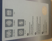
According to the UNECE Regulation 28, the horn must be able to produce at least 105dB (A) but not greater than 118dB (A). We bought the horn according to the regulation and we tested the horn and its performing fine. Our next challenge is how do we mount the horn and finding the best place to place the horn. Refer to figure 76 for the specification for our horn. We have also tested the the Horn in order to check for its frequency with our phone and a computer software.
Task 3: Understanding on the auxilary diagram
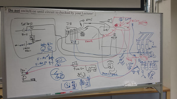
This show an auxilary circuit of the SunSpec 4. shown in figure 77. Our initial plan is like a normal convention car. When you insert your car key, the first turn is to on the 12v devices eg radio speedometer light. The next turn is to start the engine.
But after further consideration, we put into 1 single switch to turn on the entire car. The switch will be place in the auxilary. The Battery Management System(BMS) will be switch on by the auxilary switch. There is an internal relay inside the BMS that will help to switch on the HV.
After deciding how to start the SunSpec 4, we also plan out what type of switches, fuse and MCB for your circuit diagram.
The first switches that our team consider is the E-stop button. From the regulation, it stated that one must be on the exterior of the car and another one must be in the interior that must be reached by the driver.
For the exterior E-stop button, it must be flush. If we use a mushroom head type of button, the aerodynamic will be reduce.
For the interior E-stop button, we are planning the to place it beside the driver. We plan to use a mushroom head type of E-stop button so that it is easier for the driver to reach, more visible and better feeling to push it during an emergency,
For emergency use, an activation device that immediately places the Solar EV into Safe State must be provided on the exterior of the car. The activation device must be placed within a yellow disc with a minimum diameter of 180 mm. Also in the yellow disk must be a blue equilateral triangle (minimum side length 150 mm) containing a red flash, with the legend Emergency Electrical Isolation. Shown in figure 78 . In addition, there must be a clear instruction on how to operate the device (e.g. PULL or PRESS). Taken from WSC2015 regulation.
Fig 76
Fig 77

Fig 78
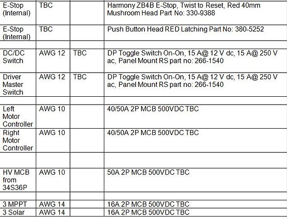
The toggle switches we used are the 3A and 6A. It will be use to ON/OFF BMS, telemetry and Battery Ventilation Fan. On-Off-On
List of items to purchase for Sunspec4 auxiliary
Circuit breaker
-
Midnite solar 15A MCB 10PCS PART NO: MNEPV15 from midnite
-
ABB 50A MCB 3PCS PART NO: M202-50A from ABB
Toggle Switches
-
Master Switch 6A 5PCS PART NO: 2508748047
-
Lockable switches for Forward Reverse 3PCS Part no: 394-443
-
Long flat lever on-off-on for left right signal 3PCS Part no: 394-469
Push Button
-
Mushroom head for E stop with latch 2PCS Part no: 241-5684c
-
Latching switches flush for e stop 22mm red ring illumination 2PCS Part no. 436-907
-
Horn/Hazard PB 2PCS Part no. 433-3168
-
Linear/rotary sensor for brake light 2PCS Part no: 317-780
Basically, these are the few items that we need to puchase for Sunspec 4 auxiliary based on the schematic electrical diagram. After we had discussion with leturers, they provide us information about what type of switches and components we should buy. Each components we will buy must refer to 2015 wsc regulations. We do online research and refer to catalog book to select the items that we want to buy.
Week 6
Task 1: Purchasing switches
After shifting all the motors and electrical components to our new solar car workshop, we begin to do motor testing. We try to layout the whole motor testing by putting the M5048-II motor on the motor tester and align everything in a linear position. Then, we wait for our lecturer to proceed on for motor testing.
Task 2: Motor testing
Our SunSpec 4 works like an convention car. By refering to Fig 79
1. Switch on the 3S4P battery to activate the 12V devices such as brake lights, BMS etc.
2. Switch on the Driver Main Switch. The relay will be activated. This step is like starting the engine of the car. When the Driver Main Switch is on, HV devices will be switch on such as motor, batteries and etc.
3. When the HV is on, solar panel will collect sunlight then produce current to charge the 34S36P batteries, 34S36P batteries will gave power to drive motor and the DC-DC converter will step down for charge the 3S4P.
4. The E-stop button will break the circuit near the relay. When the button is press, the whole circuit will be cut-off.
Isolation for LV
Car Fuse
The isolation for the LV is initially using the toggle switches to turn it on and off. Devices like Telemetry and BMS are LV and it must not be switch off during the race. Our team and lectures plan realize that toggle switches are difficult to organize and might be dangerous to the devices as driver might accidentally off it. After consideration, we would like to implement car 5A fuse to isolate the devices shown in fig 80 . This can benefit buy organizing the wire and can be easy to isolate by removing the fuse and easy to replace. We are trying to place this inside an perdesktor for easy isolation.

Toggle switches for signal lights
We would like to design the SunSpec 4 like an convention car for the driver to react. For the left-right signal, we would implement on-off-on switches. This would allow the driver to turn on their signals easier. We hope to place it near the right side of the steering so that the driver can reach easily and react like an normal car but just that after turning, drivers have to remeber to switch off the signal as we do not intent to make an automatic cut-off after using the signal lights.
For the hazard lights, we choose a DPST PB. So when the driver presses the PB, the hazard lights would light up just like an conventional car. It would be located at the center of the car and easily reach but the drivers.
Signal lights has to blink at a certain pulse. We will be using a relay to activate this function so that the signal and hazard lights will blink light how a normal car behaves.
Toggle switches for 3S4P and Driver Main Switch
Using MCB for a small current rating devices would be redundant. Due to the small current rating, we plan to use toggle switches as it is easier for the driver to switch on and off. It is light weight and can be easily organize so that the driver could reach and feel better on the toggle switches. The toggle switches will be located at the perdesktor.
E-stop button
There are 2 E-stop buttons. External and internal. The external button much be flush due to the aerodynamic and also from the regulations. This can allow other people outside the car to deactivate the car system outside the car. Another button will be located at the perdesktor which is a mushroom head that is easily feel and seen by the driver. E-stop button must be also come with an emergency sticker and written either pull or press. The button must be in the boundary of the sticker.
PB for Horn
According to the UNECE Regulation 28, the horn must be able to produce 105dB-118dB. We tested the horn after purchasing and we realize that the power supply could not sound the horn. We expected that the horn Ampere is high and hence, we use the Li-Ion 3S4P to sound the horn and it was measured 3.6A. It agrees with the regulations and the current rating is acceptable. The horn will be sounded by a PB mounted on the steering convenient for the driver to press it using their thumb to sound the horn.
Isolation for HV
MCB for Solar Panel
The isolation for HV for circuit breaker would be located before the MPPT’s. There are total 3 MPPT’s for Solar Panel A,B,C+D. Each of the MPPT’s are DP hence, we would choose a 2P MCB 10A to isolate between the solar panel’s and MPPT’s. We are choosing ABB M202-10A MCB as the solar panel will produce about 90V. After the MPPT, the MPPT will produce about 150V.
Changes to MidNite Solar 15A MCB after much consideration
MCB for Motor and controller
The controller will control the left and right motor. To isolate the motor, we place a ABB M202-50A to isolate. Both left and right motor will then be isolated. 8AWG will be used to connect from the junction box to the controller and 10AWG will be used to connect the controller to the motor.
Changes to ABB Part No: S250S-DC. Due to rating corrections
Junction Box (JB)
They will consist of LV and HV bus bar. All LV devices will be tap to the LV bus bar and HV devices to connected to the HV devices. If it its a HV device, a HV sticker must be paste.
Task 3: Understanding driver behaviour
Interior of SunSpec 4 shown in fig 81. We have planned to wait our car to arrive school then we decide where our electrical components will be placed inseide the car. This is because we need to sit inside the car to understand the driver behavior. The seat is shown in the picture above. We need to make sure these components can be easily access on by the driver and whether he feels comfortable with the position of these components. These components included MCB, Fuses, switches, emergency stop button and more. By looking at the sketch on AutoCAD to decide where these components to implement on is possible but this will create undesired result. We do not know how the driver will feel like with the position of these components, whether he is comfortable with or can be easily access on. The AutoCAD sketch also does not show every details part of the car, so it is very hard to decide where to implement these components.

We do not want have mess wiring inside our car. We when over to Pasir Ris to visit the car and plan some ideas of some components to be place at. Therefore, we decide to have one low voltage junction and high voltage junction box as seen in the fig 82. We differentiate it is because we found out that most of the Low Voltage devices are located at the front such as lights, horn and etc refering to fig 83. High Voltage devices such as solar panels, motors and etc are mostly located at the back. The box would be located at back of the car refering to fig 84. We hope that this construction will tidy up the the wiring. So when we are doing trouble shooting, it is easier for us. All the low voltage components wiring include switches and lights will be inside the low voltage junction box. Similarly, all the high voltage components wiring include solar panels and motor will be inside the high voltage box. We have to ensure that all the wirings inside two boxes will be neat and have a good isolation. Then, we plan to have LV junction box at the front of the car and the HV junction box placed at the back.
Referring to our Sunspec 3 in fig 85, we use the washing machine pipe to wrap the high voltage component wires and partially covered pipe to wrap the low voltage component wires. This year, we decide to use the transparent trunking to wrap all these wires. Therefore, we can observe the wires inside the trunking are connected to which components. This will enable us to trace the wires and repair them when necessarily. This is to provide professional look.
We hope to achieve a neat wiring look like figure above in fig 86. This enables us to rectify the wires easier and also presentable to other teams in the upcoming race.
Task 4: Implementation on wiring


Taks 5: Motor Alignment
According to week 5 task 1, we've learn how to change tires, but motor alignment is a new challenge. As our Mitsuba motor is a hub motor, motor alignment is important. If the motor is out of alignment, the motor will vibrates greatly and create a high rolling resistance on the tire. A lot of energy is lost when the tire rolls, the efficiency will drop also. Figure 87 shows a motor mounted on SunSpec 4. In order to avoid this situation happen during the race, now we are training ourselves to be able to align the motor on the wheel properly. So, we are trying to minimize the energy lost through rolling resistance during our upcoming race.

Auxiliary


Task 1: Testing DC to DC converter
According to the Sunspec 4 schematic electrical diagram, we need a dc-dc converter to step down the voltage to nominal voltage for the auxiliary devices. According to the specification, the input voltage is expected to be around 120v to 150v and the output voltage is 12v. Therefore, we bought the half brick model Vl-Joo dc-dc converter and used it for testing. Due to insufficient voltage from power supply, so we set input voltage of 95V to dc-dc converter and we get an output voltage of around 12V. The dc-dc converter works perfectly as we get our ideal output voltage of around 12V which is required for our auxiliary devices. Fig 88 shows a testing of dc-dc converter using two power supply and two multimeters and we achieve 12V step down.

Task 2: Planning components and wiring system in Sunspec4
We gather other teams to discuss where they would want their equipments to be placed. Figure 89 show that we halfly finished drawing our components and wiring system in our Sunspec4. As you can see from the figure, most of the low voltage components are installed in front of the car and high voltage components are at back. Hence, our low voltage junction box will be placed in front of the car and high voltage junction will be placed at the right back of the car. We are still deciding the position of these electrical components in the car as we have to ensure that the wiring system does not look so complicated and overlap each other. Besides of that, we are trying to place these components as closer to the junction boxes as possible so that the wires drawn from components are not long to reduce the loss of energy from battery supply. Furthermore, we are still deciding the wiring system of the telemetry box and solar panels inside our car.
Task 3: Discussing the wiring system and swtiches
Week 7 (EXAMS)
Holiday Day Week 1 & 2
After consideration with our lecturer Mr Leong and Mr Lam, we plan and finalize with this wiring diagram shown in Fig 90. This would be our wiring diagram for SunSpec 4. We would be using MidNite Solar MCB for the isolation of Solar Panels and MPPT's 15A MCB. We also use ABB 50A MCB to isolate both Motor Controllers. All negative (-ve) would be common to the High Voltage Junction Box. Challenge now is the wiring from other groups and we plan to hand it over to Zuken team to enhance our diagram.
Fig 79
Fig 80
Fig 81
Fig 82
Fig 83
Fig 84
Fig 85
Fig 86
Fig 87
Fig 88
Fig 89
Fig 90
Task 4: Designing HV junction box


First Design
We plan to design our own HV junction boxes to minimize space and to organize wire neater and nicer. The first design of the box is 250mm by 250mm and 65mm tall. We first place some lugs and calculated how many components in one bus bar then place the MCB beside to get the dimension as seen in fig 91. In fig 92 is a drawing of how our HV box will look like. Initially we didn't plan to add MCB inside the box but after consideration by our lecturer, there is a place at the corner to place the MCB to isolate the battery. We plan to place the HV box at the back of the car.
This is to prevent fault at the bus bar to protect the battery. There are 2 bus bar 3mm thick and 180mm long inside the box, positive and negative. There are total 6 holes at the top of the junction box, for the MPPT (yellow arrow), one hole for 3 wire AWG 14 positive and 3 wire AWG 14 negative. 2 holes for right motor (green arrow), 1 wire AWG 8 for positive and 1 wire AWG 8 for negative. 2 holes for left motor, 1 wire AWG 8 for positive and 1 wire AWG 8 for negative.
At the bottom, 2 holes for battery 34S36P, 2 AWG 8 wire for each hole cater for positive and negative. 2 holes for DC-DC AWG 8 wire. We also hope that this box can solve problems easily and organize all wire easily.
After that, we use straw paper to make out the prototype to see what it looks like. In fig 93 shows the interior and fig 94 shows the exterior of the HV box.
We intent to place it on the car and visualize the positioning of the box.
Fig 92
Fig 91
Fig 93
Fig 94

Task 5:Designing LV Junction box
I'm a paragraph. Click here to add your own text and edit me. I’m a great place for you to tell a story and let your users know a little more about you.

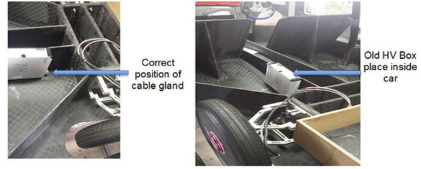
As we place our first prototype on SunSpec 4 shown in figure 95, we realize many problems such as, wiring crossing each another and cable gland sizes. We bring along our high voltage junction box to visit our solar car. We have to place the box at the back of the car to check whether the size of the box and the position of the cable glands are fixed on to the skeleton structure of the car. We realized that the position of the cable glands are wrong as the wires are not able to run through the cable glands from the bottom of junction box. This might cause crossing of wiring which is untidy. Referring to fig 95 is the correct direction of the cable gland should be.
Second Design (Why redesign?)
Second design of HV box


MPPT’s: 6 pcs AWG 14 wire, 2 pcs 18mm Cable Gland
Battery to MCB: 2 pcs AWG 8 wire, 28mm Cable Gland
DC/DC: 2 pcs AWG 14 wire, 16mm Cable Gland
Motor Controller: 4 pcs AWG 8 wire, 28mm Cable Gland
Referring to figure 97 and 98(prototype), after reconsideration, we shift all the cable glands to both sides of junction box and lower down the position of cable glands. This is due to the direction of where is the wire is going too. Example the battery (34S36P) and Motor controller is place at the back of the car hence, we planning to put the cable gland towards the right of the box so the direction of the wire is correct. This to prevent overlapping and crossing of wires for the connection. We also extend the length of the box to allow more spacing for the wire inside the HV box and upsize the cable glands to reduce the number of holes. So that more wire can pass through.
The two copper bus bars remain in a horizontal position with 8 holes drill. Hence, we plan to drill holes on the back skeleton of the car so that all the wires can be passed through and reach the cable glands on HV junction box. The MCB remains in vertical position as we also consider the human norm We lengthen the size of high voltage junction box so that the wires have enough space to run through from cable glands to copper bus bars
Single line diagram for HVDC

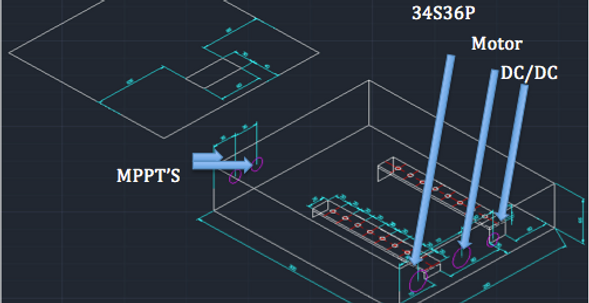
This is the single line diagram of HV junction box shown in fig 99. This is to plan and layout the wires for the HV box. As we can see from the layout, the right side cable glands are used for DC/DC converter, motor and battery wires and the left side is reserve for MPPT’s. For the DC/DC, one positive and one negative wire from DC/DC will pass through the right cable gland and connect to bus bars. At the center right, two positive wires and two negative wires from left and right motors will pass through the right cable glands and connect to bus bars. From the bottom right, one positive and one negative wire from battery will connect to the bottom of MCB and the wires from the top of MCB will connect to the bus bars also. At the left side of the box, three positive wires and three negative wires from MPPT pass through the left cable glands and connect to the bus bars. We hope that there is enough space inside the box so that the wiring is neat and not overlapping each other.

Design LV Box
The low voltage box is to allow LV decives to tap on to get their power supply. The LV box is meant for LV devices to tap their power from there. This make wiring much more neater. The box is 210mm by 165mm by 65mm. Total of 4 cable glands, 2 copper bus bar. The 2 holes on the cover is meant for the pushbutton MCB cater for the incoming 3S4P battery. This is to protect the battery and isolate the LV box. The LV box is shown in fig 100.
Battery 3S4P 2 pcs AWG 18 wire, 22mm Cable Gland
Lights: 2 pcs AWG 18 wire, 22mm Cable Gland
BMS/FAN: 2 pcs AWG 18 wire, 20mm Cable Gland
Horn: 2 pcs AWG 18 wire, 20mm Cable Gland
Referring to figure 100, we plan to have two cable glands on the right side of lv box and two cable glands at the left side of the LV box. These cable glands are located at the center side of the box so that all the wires from the components can reach the copper bus bars without overlapping each other. The size of LV box and cable glands we used are smaller than we used for HV box as the wires from LV components are thinner. Four cable glands on the LV box are enough for the connection of wires from components through cable glands and reach the copper bus bars. The two copper bus bars in a horizontal position with 6 holes drill. Most probably we will place the LV box right in front of the passenger seat, we plan to drill holes at the side of the car skeleton to allow the wires pass through skeleton from LV components to the LV box.

Single Line Diagram for LVDC
This is the single line diagram of LV junction box shown in fig 101. As we can see from the layout, the right side cable glands are used for low voltage battery (3S4P), BMS, telemetry and fan wires. At the left side, the cable glands are used for the light and horn wires. One positive wire from battery will connect to one of the push button MCB through the right cable gland and connect to positive bus bar. Similarly, one negative wire from the battery will connect to one of the push button MCB through the right cable gland and connect to negative bus bar. One positive wire from BMS and fan will share the same wire and pass through the right cable gland connect to the positive bus bar. For the Telemetry, one positive and one negative wire from light will pass through left cable gland and connect to the bus bars. On the other hand, two wires from horn will also pass through the left cable gland and connect to the bus bars inside lv box. We hope that there is enough space inside the box so that the wiring is neat and not overlapping each other.
Task 6: Testing Regenerative Braking


We also realize from the manual, there is regenerative mode. The Mitsuba motor has a regenerative function. This bring lots of benefit to us as we could regenerate and pump energy back into the battery to compensate losses. We plan to see weather is there really a regenerative function in SunSpec 3. We would use power supply and try to active the motor running. When it works perfectly, we go ahead to use the battery to power up SunSpec 3. The battery team also help us check the balance of all battery cell and also Lecturers and TSO double check the connection of the HV battery so that we could test safe.
Using power supply
Power supply and set it to 96V and placing clam meter to monitor the current referring to figure 102. Even though the controller M0896C can take in input voltage of between 70V to 150V but we only set 96V on the power supply. After supply power is on, we switch on all the MCB switches and driver main switch and then we monitor the current by pressing the linear potential meter which is also the accelerator. We using clamp meter to measure the changes of current while we slowly press the linear potential meter. By pressing fully on to the potential meter, we get an average current of 1 ampere on the reading of clamp meter. When we ramp the accelerator, it could spike about 9A.
Using battery supply
Using battery to run SunSoec 3 is shown in fig 103. The voltage supply from battery is 122V. The rest of the procedures are same as using power supply to test the motor. We also get an average current of 1 ampere on the reading of clamp meter when we fully pressed the linear potential meter during full speed. Figure 1044 show a sample reading from clamp meter while we are testing the motor. We also realize that when the potential meter is suddenly fully pressed, the current will spike up about 8A.

Holiday week 3

-
According to figure 79, the electrical diagram has slight changes. The final electrical diagram is attached in figure 105. This is a map of both high & low voltage. The changes are the following:
-
BMS, Battery Ventilation Fan and Telemetry is now can be switched on and off with a fuse and not using toggle switches.
-
Horn, signal lights and DC/DC converter is also isolated with a fuse for safety purposes.
-
The LV bus bar is isolated with a Push Button MCB.
-
HV device, isolated both positive and negative with a MCB.
-
Relay has be added to 3 of the solar panels instead of MPPT’S. So it will activate the solar panel then the MPPT’S.
The starting of SunSpec 4 has a bit of changes, previously according to 3.0, we need to switch on the auxiliary switch so all LV devices will turn on, when the driver main switch is on, HV devices will then activated.
But for the new design, the driver main switch is remove and hence, once the Master Driver Key (previous Auxiliary) is on, everything will be switched on. A switch is also added to the DC/DC converter to prevent charging to the 3S4P and to safe up power.
Components selected

Fig 95
Fig 96
Fig 97
Fig 98
Fig 99
Fig 100
Fig 101
Fig 102
Fig 103
Fig 104
Fig 105
Fig 106

Task 1: Planning components for Sunspec 4
Task 2: Layout of Control Panel
Week 11:
Task 1: Testing of M-2096 non Amophous core
Task 2: Layout of wiring on SunSpec 4
Implementation phase
Week 12:
Task 1: Testing of M-2096 Amophous core
Week 13 (HBL)
Task 1: Reconstruction of HV
We draw the layout of control panel and summit to MAE students to cut out the box according to our design. On the control panel we will have driver main switch,
We have to draw the layout according to the size and the position of these switches so that the driver is able to reach easily. For example, more frequently use switches will keep near to driver and not often use swtiches will be on the other side. So that during driving the driver will not confuse to find the switches.


As you can see from figure 109 and 110, we using power supply to test the non armophous core motors by mounting them on the jigs. The left and right motors are connected to the respective controllers. Due to the power supply is old, before we start to power up the motors we will use multimeter to double check the power supply voltage. Firstly, we set the supply voltage to 46V which is the minimal voltage, and start to increase the speed of rotation of motors. We measure the current of each contoller. We get an average current from terminal A is 8.7A, terminal B is 8.5A and terminal C is slightly different which is 7.4A. The DC current is around 1A. Similarly, we set the supply voltage to 96V and start to increase the speed of rotation of motors. We measure the current of each contoller. We get an average current from terminal A is 10.5A, terminal B is 10.8A and terminal C is also slightly different which is 9.3A. The testing result is quite good as the motors are able to run smoothly by turning the speed knob and gear box.

Basically, the figure above show the layout of wiring on sunspec4. The LV components wires are on the left side and the the Hv components wires on the right. All the LV componets will use AWG 18 wires for connection. The HV components will use AWG 8,10,12 and 18 wires which depend on what devices we are connecting. We also try to measure the the length of wires that we will implement on Sunspec4 and collaborate with all the teams to discuss their component placing and also compensating for telemetry group for their sensors to be place at.
Under supervison of Mr Lam and Mr Chua, we test the M2096 armophous core motor using new power supply. We set the power supply to 75V to both motor 1 and motor 2 and start to increase the speed of rotation of motors. The Dc current of motor 1 and motor 2 are 0.8A and 0.7A respectively. The average current from terminal A,B and C from motor 1 are 4A, 4.5A and 4A repectively. On the other hand, the average current from terminal A,B and C from motor 2 are 4.5A, 4.7A and 4A respectively. We also use techomotor sensor to measure the speed of the motors. We get average speed of 1016 rpm from motor 1 and average speed of 1100 rpm from motor 2. Both armophous core motors run more smoothly and higher speed compared to non-armophous core motors and we realize the rolling resistance is way better than the previous motor and we can conclude this motor can perform well in the race.
The next step is to play with the software to adjust to the correct setting.
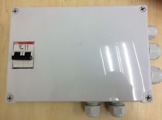
We receive the free junction box by a vendor that sponsored us in figure 114. We feel that both of the junction box made of metal is heavy weight and it is not realiable and adding weight onto SunSpec 4 is not good. We then plan to remake a lighter box and reusing the same bus bar given. We went over to Sim Lim Tower to search for junction box and then we bought 2 identical boxes.
It is PVC with a rating of IP66 with a dimension of 170 x 250 x 80. 2 of these boxes will be used for HV and LV.
The design of the HV box is almost the same as the previous design. But due to the space constraint inside the box, we shift 2 cable gland for the MPPT'S down to compensate the space. We cut out a space to expose out the MCB and drill holes for the cable gland. Motor and Battery will using PG 21, DC - DC and MPPT's using PG 16. Shown in figure 115.
The design of the HV box is almost the same as the previous design. But due to the space constraint inside the box, we shift 2 cable gland for the MPPT'S down to compensate the space.


Old
New
Task 2: Reconstruction of LV
We also found out the LV box is also heavy weight and hence we plan to reduce the weight and the size is the same as the new HV box. The position of cable gland remain the same and it is PG 16. The old heavy Lv box is in figure 116 and the new hv box is shown in figure 117.


New
Old
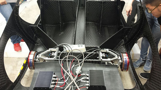
Two non armophous core motors are mounted on the wheel of Sunspec4 and controllers are set at the back of the car. We use power supply to test the motors and let the MAE students to check the rotation of motors on the wheel of car. By doing so, they are able to check whether the motors are good in conditions. We realised that the right motor vibrates more and produces undesired noise compare to left motor. Hence, the MAE students troubleshoot the problem whether it is not properly wheel mounted or there is a problem on the motor. After we finished testing, we proceed on to test the non armophous motors by mounting them on the jigs.
Fig 108
Fig 109
Fig 110
Fig 111
Fig 112
Fig 113
Fig 114
Fig 115
Fig 116
Fig 117
The new box we bought from Sim Lim Tower is an empty box without any holes at the side of box. Hence, we need to drill holes at side of the box to fix cable gland size and drill four small holes in the centre of box to fix the copper bus bar inside which is shown in figure 118. After we finished drilling the holes, we file them to make them smooth which is in figure 119.
Fig 118
Fig 119
After fabricating the HV boxes, its time to mount it on the car.
We did put into consideration of the amount of spacing for the wire and weather the driver or passenger can reach to the Circuit Breaker on stretch.
Hence we place the box on the left side of the canal to meet this requirements to fulfil a neat and safe wiring.